Ruptela - Installation Guide
Installing a GPS tracking device in your vehicle is not a complicated task, but it is essential to take safety precautions, as such the installation should only be carried out by a qualified Auto Electrician.
Usually, it takes approximately 2 hours to set it up depending on the complexity of the vehicle’s wiring structure. For a better understanding of Ruptela Eco4+ GPS device installation (basic installation with no fuel/temperature/door sensors connected), read the following instructions.
*Read more on the Do’s & Dont’s of GPS device installation at the end of this document.
Kit/Box Contents
- Ruptela GPS tracking device (ECO4+)
- M2M SIM with data package
- 20 pin I/O cable
- 3M Scotchlok, Connectors, Double sided tape, and Zip ties
Tools required
Screwdriver set, Plier, Multimeter and Wire Stripper/Cutter/Crimper.
Getting started with installation
Step 1: Scribble down required info
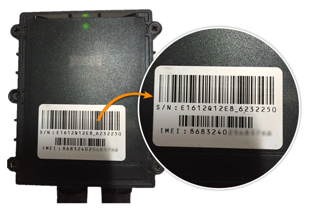
Before installing the device, you need to note down International Mobile Equipment Identity (IMEI) number of the GPS tracking device and the SIM GSM number.
Then insert the GPRS enabled SIM card to the device. You may as well download the vehicle addition template to record vehicle information.
Then insert the GPRS enabled SIM card to the device. You may as well download the vehicle addition template to record vehicle information.

*IMEI is a unique number to identify GSM, WCDMA, and iDEN mobile phones, satellite phones, as well as some telematics devices that works as a unique identification code. This 15-digit number is usually printed either on the bottom of the GPS tracking unit or the device case; you require IMEI to register the GPS tracking device on the fleet management software.
Step 2: Connect the wires
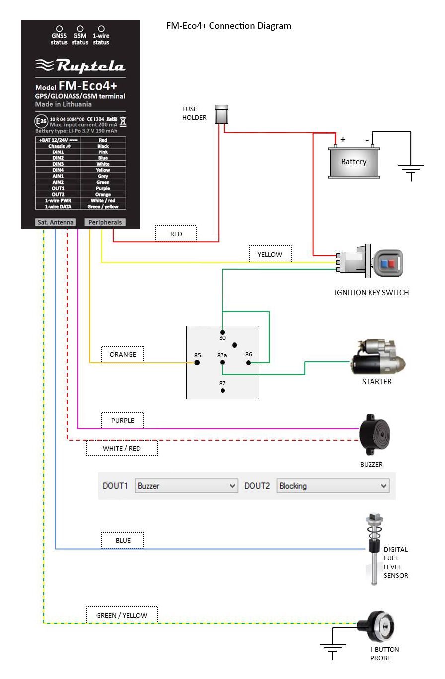
Connect RED Wire/POWER; BLACK Wire/GROUND and YELLOW Wire/IGNITION, ie the (+ve) Red wire (of GPS device) to one end and the power source of the vehicle to the other end of a 1Amp fuse. Secure the fuse to the instrument chord with a cable tie.

Connect Black wire (-ve) on the harness to Chassis Ground (any bolt or wire with -ve power).
Connect Yellow ignition sense wire to the vehicle’s ignition source to help track ignition ON/OFF events.
Please consult the vehicle wiring diagram to locate the ignition wire. You can verify the vehicle ignition wire by measuring the vehicle’s operating voltage while the engine is running.
Once identified, connect the ignition wire to the FUSE BOX with a 3M Scotchlok so that it will snap into place and will get it properly seated.
Please refer to the connection diagram below, for a detailed view of the wires & connectivities.
Step 3: Mount the GPS device
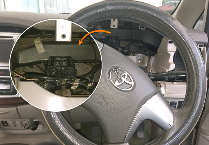
One of the quickest and the best place to mount a GPS tracking device or a GPS tracker is under the dashboard or an exterior location in a horizontal position with a clear view of the sky.
You may experiment with placing the tracking device at different locations on the vehicle to determine the best reception for the desired level of concealment.
If the device has external GPS antenna then place the antenna underneath the dashboard or wherever convenient using double-sided sticky-tape to ensure it’s firmly fixed there.

Once you’ve placed the GPS tracker in the vehicle, you’re all set.
Step 4: Connect the wire socket
Connect the wire socket and GPS/GSM antenna (of those with external antenna) to the GPS device.
Step 5: Verify the Installation
As soon as the device is powered on, both green LEDs (GPS & communication) will flash on and off while searching for signals. When full signal strength is achieved, both LEDs will continuously illuminate.
Step 6: Ring the GSM number
In order to validate functionality, we need to ring the GSM mobile number of the SIM. If it rings or responds with a busy note, you can safely assume that the device is functioning properly.
If there is no response, you may have to re-insert the SIM card and check the wiring again.
Step 7: Check device communication
Please Log into the platform with your credentials to make sure the device communicates with the server.
Note: Make sure that the IMEI no’s & mobile no’s you updated against the vehicles are correct.
*Do’s & Dont’s during installation
To avoid mishaps while installation, make sure the vehicle ignition is turned off before initiating wire connections.
-
Usually for the light vehicles/cars, the nominal voltage is 12V DC whereas for trucks/heavy vehicles; it could be 24V. However, most of the GPS devices fall in a connectivity voltage range of 6V – 30V.
-
It is always advisable to disconnect the appropriate jumpers /connections of vehicle’s power supply during the GPS device installation; this is to avoid short circuits and wiring damages. Make sure the wires stay disconnected while mounting/dismounting the device.
-
Secure all wiring with Scotchlok, cable connectors, and electrical insulation tapes. Never allow any bare wiring to remain exposed; connections must be least visible. Ensure additional insulation if wires go through a visible/exterior region, so as to avoid short circuit/wiring damages.
-
GPS tracking devices could be mounted in a zone of limited access, so none has direct access to the instrument. Keep connecting wires as discreetly as possible, making it less visible and hard to notice.
-
For the safety of personnel, device & vehicle, avoid connecting device wires to the board computers (ECU) or control units. Ensure that you fasten wires to other wires/non-moving parts and not to fasten near heat emitting and moving objects as friction/heat emission may cause sparks leading to short circuits.
-
While connecting ignition wire confirm if it’s the real ignition wire (power supply available only when the ignition is on). Using a multimeter, check power flow by turning on/off the engine.
-
Connect the vehicle’s ignition to the ignition relay output of the device. If no particular ignition wire is available (possible in certain heavy machinery), any other relay with power output (when the ignition is on) can be chosen. Once again, use a multimeter to confirm the power flow by turning on/off the engine.
-
While connecting to the power source, please make sure you connect the device to a wire that has 24/7 continuous power supply. The device has to be powered all the while; the engine is switched ON/OFF.
-
For safety reasons, make sure you check the voltage flow from power source using a multimeter when the device is connected/disconnected.
-
While connecting ground wire, make sure you connect the ground wire to the vehicle frame/metal parts say, a bolt fixed to the vehicle frame.If the wire is tied to a bolt, make a loop in the wire at the bolt end, so it may not get loose & go disconnected. For better contact, scrub off paint from the area where the loop is connected.
-
Do not place the GPS device near metal surfaces/radio/speakers/alarm systems; may weaken GPS signal transmission. Avoid placing the GPS device next to heat/moving parts; it may cause sparks leading to short circuits.
-
Device manufacturers recommend the device to be mounted rigidly on surface areas open to the sky (dashboard, rear windscreen, etc.) where exposure to GPS satellites is considerably high.